|
|
Alaska Section, American Water Resources Association
Scott Maclean, Alaska Section AWRA Northern-Region Director
I would like to invite you to the October 2001 Brown-Bag presentation by Emily Youcha.
Please note this meeting is the second Wednesday in October. We look forward to seeing you, please feel free to
bring a colleague to the meeting.
October 10, 2001
Alaska Section AWRA, Northern-Region Brown-Bag Presentation
Alaska Department of Natural Resources, Large Conference Room
Noon to 1300
"Development of a 3-D Hydrogeologic Model of Ester Dome, Alaska"
Emily Kristen Youcha
Water and Environmental Research Center
University of Alaska Fairbanks
Fairbanks, Alaska 99775
Youcha, Emily K., (Water & Environmental Research Center, University of Alaska Fairbanks, Fairbanks, AK, 99775, fteky@uaf.edu)
Lilly, Michael R., (Arctic Regions Supercomputing Center, University of Alaska Fairbanks, Fairbanks, AK, 99775, mlilly@arsc.edu)
Hinzman, Larry D., (Water & Environmental Research Center, University of Alaska Fairbanks, Fairbanks, AK, 99775, ffldh@uaf.edu)
ABSTRACT
We are conducting a geohydrologic investigation of Ester Dome, an upland-dome aquifer system located seven
miles west of Fairbanks, Alaska. The application of MODFLOW, a finite difference ground-water flow model, to Ester Dome will
aid in the interpretation of the overall hydrology. The application of an appropriate ground-water flow simulation is very
involved and initial steps entails developing a conceptual model and turning it into a numerical representation of the hydrogeology.
To begin the modeling process, we identify the boundaries of our aquifer systems. Major hydrogeologic features are defined. Next,
we generate a land surface representation using a digital elevation model (DEM) and create two-dimensional surface grid. Then we
add the third dimension, which consists of several model layers. The main constraint of developing this hydrogeologic model lies
in the lack of information about the subsurface geohydrologic system. We must define the geology of Ester Dome to develop the
hydrogeologic model and interpret the hydrologic processes. Geology and hydrology data sets are limited therefore the model must be
limited in its complexity.
At Ester Dome, the bedrock is composed of quartz-rich Fairbanks Schist, Muskox Schist, and Muskox Amphibolite. Additionally, several
Mesozoic intrusives outcrop around Ester Dome. The valleys are filled with quaternary alluvial deposits and the dome is covered with
deposits of loess of varying thickness. The fracturing of the bedrock and the structural geology are important controlling factors of
the ground-water flow patterns. A large-scale northeast-trending fault system cuts across the eastern portion of the dome resulting in
increased aquifer transmissivity. Additionally, permafrost, present in many of the valley bottoms and the north-facing slopes, may act
as a leaky locally-confining layer. These geologic controls can be assigned into zones with differing aquifer properties within the model.
Visualization techniques simplify the model verification process. Displaying the geology and the hydrogeologic properties in three
dimensions will allow us to more easily understand subsurface characteristics of Ester Dome. Computer applications allow us to generate
land surfaces and model layers of varying thickness. These applications are also used to visualize the terrain, geologic features, and
important hydrologic processes of an interior upland-dome aquifer system.
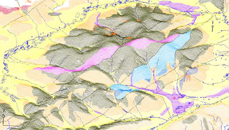
Figure 1. DLG hydrology and geology data draped over a digital
elevation model (DEM). The visualization technique of draping allows one to place DLG data over a DEM and solve for the z (vertical)
component of a two-dimensional element. We can now find the elevation of streams and lakes. It is now easier to identify zones of
changing geology for aid in the development of a numerical ground-water flow model.
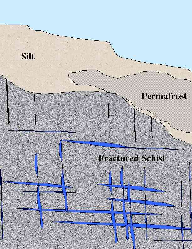
Figure 2. Generalized cross-section at a low elevation location on the dome. The fracturing of
the bedrock is the primary control on groundwater flow and storage in the bedrock aquifer. The silt layer can be up to 100 ft thick.
Permafrost may exist and block recharge into the aquifer.
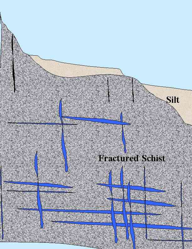
Figure 3. Generalized cross-section at a mid- elevation location on the dome. The silt layer
decreases as elevation increases. The silt layer may be up to 35 feet thick. Water may infiltrate through silt layer if the
evapotranspiration is low and enter the fractures in the bedrock.
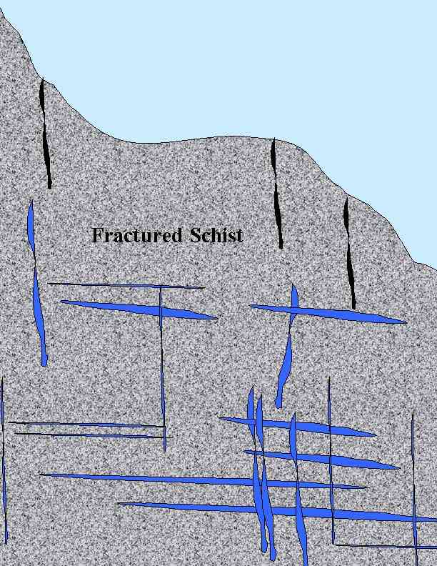
Figure 4. Generalized cross-section at a high- elevation location on the dome. There will be
0-5 feet of silt above the bedrock. Water can easily infiltrate into the fractures. The high elevations are a major source of
recharge on the dome.
Please visit our project Internet site:
www.uaf.edu/projects/ester/.
|